Aggregate level snapshots – turn them off!

A company we deal with had a pretty nasty problem recently. They were doing some major VMWare changes, including networking, and were using Storage VMotion to move from one datastore to another, on the same aggregate.

Sounds good, right? Well, there’s a well intentioned, historic, feature in NetApp’s Data ONTAP, of aggregate snapshots. The problem this company faced was due to aggregate level snapshots – while they are set to auto-delete, the blocks are not immediately freed (but the space looked available). There is a low priority free space reaper process that actually makes the blocks writable again. With the blocks unavailable, the aggregate was essentially full, leading to the usual result that WAFL exhaustion leads to, of glacial latency, which reduces the effectiveness of the space freeing process too, making it even worse. And in this case, a whole company going home. Background freeing of blocks is one of those features that makes sense – but as aggregates got bigger and bigger, and over 16TB, there exists a greater impact of whole-volume scan operations.

Normally you make snapshots of volumes, for connected system backups, recovery, etc. Aggregate level ones were a failsafe of last resort for ONTAP. From really early days, NetApp systems have had a battery to keep the NVMEM cache alive, even if the system looses power. When it comes back on, those changes are flushed to disk, and WAFL is once again consistent. The batteries used in the time I’ve dealt with NetApp have allowed for a 72 hour power outage. At times, however, this is not enough. ONTAP will boot, and find WAFL is inconsistent, and run essentially a fsck (wafliron). Usually that works. Sometimes, it doesn’t, and then you have a Very Big Problem. Aggregate level snapshots can save you here – the same way a LUN snapshot might save an attached system.

This all changed with the FAS8000 series – these systems have a battery too, but they use it to de-stage the NVMEM to an SSD. This means they can withstand outages longer than 72 hours. Which means there is no need for aggregate snapshots on the FAS8020, FAS8040, FAS8060 and FAS8080EX systems. I’d go so far as to turn them off on all systems. After the problems this company faced, I’ll be doing it for everyone.

There is one downside – aggregate snapshots can save you if you delete the wrong volume. You move any other volumes off the aggregate (yay cDOT), assuming you have another one, then revert the aggregate. This risk is usually addressed with snapvaults/snapmirrors/backup software, but it’s worth remembering. Aggregate snapshots are also used by syncmirror and Metrocluster, as outlined in this article, but in my market segment, these aren’t major uses.

This KB from NetApp recommends they be turned off for data aggregates, which like flow control on 10GbE ports, makes you wonder why this isn’t the default setting. So, check your systems folks, and turn off your aggregate snapshots, especially if you have FAS8000 systems.
Converting a NetApp FAS22xx or FAS25xx or AFF system to Advanced Drive Partitioning

ONTAP 8.3 is out right now as a release candidate, which means you can install it, but systems aren’t shipping with it. If you’re installing a new one of these entry level systems, consider carefully if it’s the right choice. From my point of view, it is, as you get much better storage efficiency. You should plan to do an upgrade from 8.3RC1 to 8.3 in Feb-Mar 2015, but with Clustered ONTAP, and the right client and share settings, it can be totally non disruptive (even to CIFS). It’s worth noting too, that for now at least, if you need to replace an ADP partitioned drive, you will probably need to call support for assistance (but it’s a free call, and they love to learn new stuff)

If you want to convert straight out of the box, it’s pretty easy:

  1. Download ONTAP 8.3 from support.netapp.com, the installable version, and put it in an http accessible location
  2. Control-C at startup time to get to the boot menu. Choose option 7 – install new software first, and enter the URL of the 8.3RC1 image from your webserver
  3. Once 8.3 is installed on the internal boot device, boot into maintenance mode from the boot menu and unassign all drives from each node – this isn’t covered in NetApp’s current documentation, but is required
  4. Reboot each node, and then choose option 4 – wipeconfig. Once the wipe is finished, the system will use ADP on the internal drives and be ready to setup

Setup of the FAS22xx and FAS25xx systems can be as easy or as complex as you’d like. They come with a USB key to run a GUI setup application, so you never need to touch the serial connection, but I’ve never used it, and the version on the key probably doesn’t support 8.3RC1, so I just do initial node and cluster setup from the CLI. Another great benefit with 8.3 is that there is now a built in OnCommand System Manager on the cluster management – so no need to ensure there’s always a machine with the right version of Java and Flash on.

Theoretically, you might be able to do a conversion to ADP with data in place by relocating all of the data to one node, and unowning and reformatting the other one, then re-joining to the cluster. I haven’t been in a position to try it, but if you have, I’d be interested to know how it went (email me@thisdomain). Some caveats on an ADP conversion – you need to have at least 4 disks per node for ADP – so the 3 current root aggr drives, and one spare. Ideally re-locate your data to the surviving node using vol move, not aggregate relocation. Then once one node is converted, vol move everything to a data aggregate the converted node, then do the same thing to the unconverted one.

Disk slicing gives you a very valid option of a true active/passive configuration, one which was never really possible with even 7 mode. The root and the data partitions do not need to be assigned to the same node. You can assign all the data partitions to one node, while just leaving enough root partitions on the passive node, or go for the traditional active/active of two data aggregates – one per node. There are some pretty big caveats for disk spares and the importance of quick replacement of failed drives, but on a FAS2520, it’s probably worth it.

I have started writing a post on active/active vs active/passive configs a couple of times, but put it off in favour of waiting till ADP was available. The basic thought is that you want a node to be able to takeover for its HA parter without service degradation, so you want to keep each node below 50% utilization, so it would be the same as running all workloads on a single system, but maybe you’ll accept some degradation in favour of getting more use out of the system. You have lots of choices. One thing to consider is processor affinity – with more processor cores, there’s less need to schedule CPU time to volume operations, and running on more processors (ie, both nodes) gives you access to more cores. But on a FAS2520, how many volumes are you likely to have?

Clustered ONTAP 8.3 – No more dedicated root aggregate!

O frabjous day! Callooh! Callay! ONTAP 8.3 is out, and with it, the long promised demise of the dedicated root aggregate for lower end systems!

To re-cap – NetApp has always said – have a dedicated root aggregate. But until Clustered ONTAP, that was more of a recommendation, like, say, brush your teeth morning, noon and night. When you only have 24 drives in a system, throwing away 6 of them to boot the thing seems like a silly idea. The lower-end (FAS2xxx) systems represent a very large number of NetApp’s sales by controller count, and for these systems, Clustered ONTAP was not a great move because of it. With 8.3 being Clustered ONTAP only, there had to be a solution to this pretty serious and valid objection, and there is – Advanced Disk Partitioning (ADP).

What is ADP? Basically it’s partitioning drives, and being able to assign partitions to RAID groups and aggregates. Cool, right? Well, yes, mostly. ADP can be used on All-Flash-FAS (AFF), but that is out of scope for this post. There are some important things to be aware of for these lower end systems.

  1. Systems using ADP need an ADP formatted spare, and then non-ADP spares for any other drives
  2. ADP can only be used for internal drives on a FAS2[2,5]xx system
  3. ADP drives can only be part of a RAID group of ADP drives
  4. SSD’s can now be pooled between controllers!

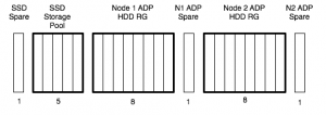
If a system is only using the internal drives, chances are, it is going to be a smaller system, and most of these don’t matter. The issue comes when it is time to add a disk shelf. Consider the following ADP layout system, assuming one data aggregate per controller:

ADP-24-disksADP-24-disks


If we were to add a shelf of 24 disks, and split it evenly between controllers, we would need to do some thinking first. We can’t add it to the ADP RG, and we need a non-ADP spare, for each controller. With ADP, and our 42 (18+24) SAS drives (21 per controller), we have used them like this:

  • N1_aggr0
  • N1_aggr1_rg0 – 6 data, 2 parity
  • N1_aggr1_rg1 – 9 data, 2 parity
  • N1 ADP Spare – 1
  • N1 Non ADP Spare – 1
  • N2_aggr0
  • N2_aggr1_rg0 – 6 data, 2 parity
  • N2_aggr1_rg1 – 9 data, 2 parity
  • N2 ADP Spare – 1
  • N2 Non ADP Spare – 1

For a total of:

  • 8 parity
  • 4 spare
  • 30 data

If we didn’t use ADP, we’d be using them like this:

  • N1_aggr0 – 1 root, 2 parity
  • N1_aggr1_rg0 – 15 data, 2 parity
  • N1 Non ADP Spare – 1
  • N2_aggr0 – 1 root, 2 parity
  • N2_aggr1_rg0 – 15 data, 2 parity
  • N2 Non ADP Spare – 1

For a total of:

  • 8 parity
  • 4 spare
  • … annnd 30 data

I toyed with running the numbers on moving the SSD drives to the shelf, meaning we could have larger ADP partitions used in RAID groups, but that still bites you in the end, as you will end up with the same number of RAID groups, but less balanced sizes as more shelves are added.

If we move to 2 shelves – 66 (18+24+24) SAS drives, we could use them like this with ADP:

  • N1_aggr0
  • N1_aggr1_rg0 – 6 data, 2 parity
  • N1_aggr1_rg1 – 9 data, 2 parity
  • N1_aggr1_rg2 – 10 data, 2 parity
  • N1 ADP Spare – 1
  • N1 Non ADP Spare – 1
  • N2_aggr0
  • N2_aggr1_rg0 – 6 data, 2 parity
  • N2_aggr1_rg1 – 9 data, 2 parity
  • N2_aggr1_rg2 – 10 data, 2 parity
  • N2 ADP Spare – 1
  • N2 Non ADP Spare – 1

For a total of:

  • 12 parity
  • 4 spare
  • 50 data

Or this without ADP:

  • N1_aggr0 – 1 root, 2 parity
  • N1_aggr1_rg0 – 15 data, 2 parity
  • N1_aggr1_rg1 – 10 data, 2 parity
  • N1 Non ADP Spare – 1
  • N2_aggr0 – 1 root, 2 parity
  • N2_aggr1_rg0 – 15 data, 2 parity
  • N2_aggr1_rg1 – 10 data, 2 parity
  • N2 Non ADP Spare – 1

For a total of:

  • 12 parity
  • 50 data
  • 2 spare

At 3 shelves, the story changes.. 90 (18+24+24+24) SAS drives, we could use them like this with ADP:

  • N1_aggr0
  • N1_aggr1_rg0 – 6 data, 2 parity
  • N1_aggr1_rg1 – 9 data, 2 parity
  • N1_aggr1_rg2 – 10 data, 2 parity
  • N1_aggr1_rg3 – 10 data, 2 parity
  • N1 ADP Spare – 1
  • N1 Non ADP Spare – 1
  • N2_aggr0
  • N2_aggr1_rg0 – 6 data, 2 parity
  • N2_aggr1_rg1 – 9 data, 2 parity
  • N2_aggr1_rg2 – 10 data, 2 parity
  • N2_aggr1_rg3 – 10 data, 2 parity
  • N2 ADP Spare – 1
  • N2 Non ADP Spare – 1

For a total of:

  • 16 parity
  • 4 spare
  • 70 data

Or this without ADP:

  • N1_aggr0 – 1 root, 2 parity
  • N1_aggr1_rg0 – 19 data, 2 parity
  • N1_aggr1_rg1 – 18 data, 2 parity
  • N1 Non ADP Spare – 1
  • N2_aggr0 – 1 root, 2 parity
  • N2_aggr1_rg0 – 19 data, 2 parity
  • N2_aggr1_rg1 – 18 data, 2 parity
  • N2 Non ADP Spare – 1

For a total of:

  • 12 parity
  • 74 data
  • 2 spare

So, a couple of conclusions:

  1. ADP is good for internal shelf only systems
  2. ADP is neutral for 1 or 2 shelf systems
  3. ADP is bad for 3+ shelf systems
  4. ADP is awesome for Flashpools (not really a conclusion from this post, but trust me on it? 😉


As a footnote: savvy readers will notice I’ve got unequally sized RAID groups in some of these configs. With ONTAP 8.3, the Physical Storage Management Guide (page 107) now says:

All RAID groups in an aggregate should have a similar number of disks. The RAID groups do not have to be exactly the same size, but you should avoid having any RAID group that is less than one half the size of other RAID groups in the same aggregate when possible.

This is in comparison to ONTAP 8.2 Physical Storage Management Guide (page 91) which says:

All RAID groups in an aggregate should have the same number of disks. If this is impossible, any RAID group with fewer disks should have only one less disk than the largest RAID group.


Out-of-band Management ports on NetApp – e0M vs SP vs Serial (and BMC!)

One of the things I’ve seen new (and sometimes existing..) customers to NetApp be most confused about, are the various ways of connecting to the system for management.

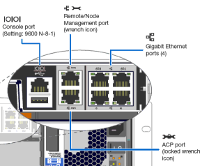
Over the years, there have been a couple of different out of band management systems (RLM and BMC are the older systems, SP on the newer ones). This post focuses on systems with Service Processor, or SP, as used in the FAS2200, FAS2500, FAS3100, FAS3200, FAS6100, FAS6200 and FAS8000 families. Lets start by going through the physical ports on the back of the controller. Where the ports are varies slightly by model, but the icons are consistent.

netapp-management-ports

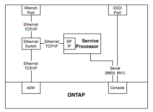
A common question is “ok, so the wrench port is e0M, why doesn’t it just say that?”. The short answer is that it isn’t – although you could be forgiven for making that guess. Even NetApp’s label set for Clustered ONTAP includes an e0M cable label, despite their systems not having a specific port labelled e0M. Let’s look at how the ports connect up, from the point of view of an administrator:

netapp-management-block


From this simplified block diagram, you can see how they all relate. The port on the outside of the box actually connects to a switch inside the box, and that has both ONTAP’s e0M and the Service Processor’s IP interface connected to it. It’s almost literally running Ethernet on the motherboard traces (it’s actually something called RMII, not normal 802.3, but close enough). The internal switch is unmanaged, which is why you can’t do VLANs over that port. To clarify some more – the service processor is an independent CPU, with its own RAM, flash and OS running on it. It talks to ONTAP very closely, obviously, and to sensors throughout the system, but it’s separate to the main kernel running on the x86 CPU that runs ONTAP.

On 7-mode systems, e0M is just another interface in ONTAP, but in Clustered ONTAP, it can only be used for management LIFs, not data LIFs (or Cluster LIFs). On the FAS2500 and FAS8000, the wrench port, and therefore e0M, are finally 1G, but on previous systems, it’s only 100M. On 7-mode systems, you have to be careful – you don’t want it on the same subnet as any of your data service IPs, or traffic might go out through it, instead of a 1G or 10G port. To stop this, set “options interface.blocked.mgmt_data_traffic on” for all systems (running ONTAP 8.0.2 or higher), but ideally put it on a different subnet. It’s best practice to have, at the very least, a different OOB subnet to data services.

From our diagram again, if you need to do something like monitor boot/shutdown/reboot during an ONTAP upgrade, you can either connect to the Serial Console or the SP IP – the output is the same. I’ve done lots of remote upgrades this way. Once the system is up, and the SP is configured, there’s almost never a need to use the Serial Console again. The SPs don’t talk to each other, so if one node is online and the other is offline, you can’t use the online node to connect to the offline one.

If you’re the type who like managing your 7-mode NetApp from the command line, you would normally SSH into the e0M IP address, while for Clustered ONTAP, you would normally SSH to the Cluster Management IP. You could go from the SP to the system console, but that will be limited to 9600bps output through the serial connection, and if you’re looking at a lot of text, or pasting a lot of text, that can be limiting. For using GUI applications like OnCommand System Manager, you connect to the e0M IP on 7-mode, and the Cluster Management IP on Clustered ONTAP Systems.

A final question I’ve heard is “what is that USB port for?”. Officially, for regular users, it’s unsupported. Unofficially, you can use it to charge your iPhone while its running in hotspot mode, or to power your Airconsole.

Could this all be made simpler? Well, there are good purposes for all of the different IPs and interfaces you might use, so I’m not 100% convinced it could be. Everything new is complex initially, but once you get a handle on it, it all makes sense. Hope this has helped you!

Edit: 2018-07-11

Since writing this article, we’ve released some new platforms, which enable the USB port while at the boot menu, have faster serial ports, and move from an SP to a BMC. They’re pretty similar, except the BMC doesn’t tap into a serial link to the ONTAP controller – it relays it over an internal network, and it doesn’t share the wrench port with e0M anymore.

Autosupport stopped working

I installed a Clustered ONTAP System about 4 months ago, and I’ve been working with the customer since then on migration of their several hundred workloads onto the system in a staged approach. While doing a regular checkin, I noticed that Autosupport had stopped working on three of their 4 nodes, despite working when I finished the initial build.

Some checks of logs and within the organization showed that it had stopped working at the same time that they had changed their mail server IPs. Easy, you think. Maybe I put in the IPs into the autosupport setup? Checked that, nope, it goes to the hostname. Well, maybe I put in an /etc/hosts entry? (system services hosts show) – nope, wasn’t that. Checked autosupport’s destinations were configured the same on all four nodes – and they were. Maybe there’s a firewall issue? Ping from the node management LIF to the SMTP servers all works. Maybe it’s a specific SMTP firewall block? Used debug mode systemshell and tcp_client (note: don’t try this at home..) – that all worked. I got their firewall and exchange admins to check logs for the node management LIFs trying to make connections, and no attempts, other than my tcp_client ones. Ran pktt on all interfaces with target IPs of the mailhosts, and found no attempts to send out from e0M (home of the node-mgmt LIF), only one of the data LIFs. NetApp KB 3012724 talks about LIFs, and has this to say on the topic:

Clustered Data ONTAP 8.2.x:

  • AutoSupport is delivered from the node-mgmt LIF per node.

Looking through the autosupport history, the attempts fail, and the last error recorded is “FTP: weird server reply”. Uhh.. transport can be either http, https or smtp. Why is it mentioning FTP?

NetApp KB 201727 shows how to access debug logs for autosupport. I did that and saw the error message of “421 Service Unavailable”. Remember the FTP error? Well, that dear readers is because your NetApp, at its heart, is a big FreeBSD box, and it uses curl to send autosupport emails. And when curl gets a “421 Service Not Available” response from the mail server, that’s what it does.

Looking at the pktt logs closer, it’s because the autosupport email is going out of one of the data LIFs for an SVM on the host. Why would you suddenly decide to do that?! Well, let’s look at KB 3012724 again..

By default, routes for the node mgmt LIF have a lower (more preferred) metric than routes of data LIFs. However, the metric is used as a tie-breaker. The more-specific route to the destination will always be picked regardless of the metric.

..

Case 3 – The node-mgmt LIF and data LIFs on different subnets, destination is on the same subnet as the data LIFs. The implicit subnet route of the data LIFs (which isn’t seen in ngsh) will be the most specific route to the destination, and will therefore be the selected route. A data LIF will be used.

So, despite the earlier assurance that autosupport uses the node-mgmt LIF, the actual story is somewhat more complicated. It uses the node-mgmt LIF, unless it likes another one better. As for why only one of the 4 nodes worked? Well that node didn’t have any SVM LIFs on the same subnet as the mail servers, so it didn’t try using them to send the ASUP email.

So what do you do? You can either create individual host routes (/32) in the routing group for the node admin SVMs, or create a subnet route in there to prevent it occuring if IPs change again. I also found (as did it seems another posted on NetApp Communities), that setting the metric lower didn’t solve the problem, you had to set the metric to “1”.

Going forward, part of my system installation will always include a route for the mail server in the routing group that the node management SVM uses.